Home
STERLING by McDonough
Instructions to Set Up and Grind a Drill

Always use safety glasses when operating this machine. Clean machine daily.

Before assembling, thoroughly remove all protective grease coating from all parts. Test grinding wheel for possible flaws or fractures. (Suspend wheel thru center hole and tap at several places with piece of metal. A dull sound indicates a defect and grinding wheel should not be used). Install grinding wheel and parts, make electrical hookup and your grinder is ready to operate. Always let a new wheel run for a full minute before dressing or using it. By adhering to the following operating instructions you can expect perfect results.

DRESSING THE WHEEL. A clean, free cutting grinding wheel face is important for accurate grinding. This condition is assured by frequent wheel dressing. Operate the built-in diamond wheel dresser as follows:

1. Loosen knurled lock nut and back out the diamond until the point clears the face of the wheel.
2. Swing dresser in front of wheel and feed in dresser until the diamond point contacts the wheel face. Snug up lock nut.
3. Start wheel and swing the dresser back and forth across the wheel. Feed diamond in and repeat until wheel face is flat and clean. (A relatively coarse and open wheel face can be produced by a slightly deeper cut with the dresser and a rapid pass across the wheel. Conversely, a finer grinding face can be produced with a light cut and a slow pass across the wheel. The coarse wheel is helpful when grinding damaged drills and the fine finish is ideal for small drills and finish grinding all drills.)
4. Swing the dresser out of the way for grinding.

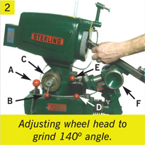
SETTING UP THE POINT ANGLE. The design of the STERLING Drill Grinder is based on the conical development principle which insures uniform clearance on the cutting edge from the outside of the drill to the point. To set the drill point angle release clamp “D” and move lever “A” forward to a horizontal position. This moves the drill holding unit away from the wheel, providing working clearance. Next, release clamp “B” and adjust hand wheel “C” to the desired drill point angle (hand wheel “C” is graduated in 1º increments and marked at 1/2 of the included angle). Lock clamp “B”. Select a drill stop to correspond to the hand wheel setting and mount it on the end of the drill holding Vee trough. (See photo 2 above)

SETTING UP TO GRIND A GIVEN DIAMETER DRILL. Release clamp “E” and move the entire drill holding unit in or out until the pointer on the drill diameter scale corresponds with the diameter of the drill to be ground. Lock clamp “E”. Turn hand wheel “F”’ until the proper pointer on the drill clearance pointer on the drill clearance gage corresponds with the diameter of the drill to be ground. Move lever “A” until the drill stop at the end of the drill holding trough clears the face of the grinding wheel by approximately 1/32". Swing the drill holding unit carefully to be sure that the drill stop will clear the wheel when it is swung through the entire arc. If the drill stop hits the wheel move lever “A” until there is at least 1/32" clearance. Lock clamp “D”. (See photo 2 above)

GRINDING THE DRILL. Release the knurled lock screw on the drill feed block (Assembly “G” photo 3) and lay the drill to be ground into the drill holding Vee trough. Slide drill feed block “G” up until drill point clears wheel by 1/32". When locating the drill in the drill holding angle always make sure that the flute edge is in contact with the drill stop blade. Turn on the motor and feed the drill into the wheel by turning feed screw “H”. Feed drill in until it contacts the grinding wheel when the drill holding unit is swung through its full arc. Grind a small amount from one lip of the drill then turn the drill over and grind an equal amount from the other lip using the same setting on the feed screw “H”. Grind the lips alternately until the proper drill point is achieved. Always make sure that both lips are ground on the same setting of feed screw “H” on the final grind. Always use a fine feed on feed screw “H” to prevent burning the drill cutting edge.

GENERAL INSTRUCTIONS. It is possible to change the existing setting by adjusting the small screws on the drill stop plates. If you are getting too much web angle, turn the small screw out. To correct too little web angle turn the small screw in. See “I”, photo 4.

When grinding 3 or 4 flute drills follow the same procedure that you would use on a 2 lip drill except swing the drill holding unit only enough to sharpen the leading edge of the lips. This will provide correct primary clearance. It may be necessary to off-hand grind the secondary clearance using a pedestal grinder.

Drills with shanks larger than the drill size can be ground on STERLING Drill Grinders. Adjusting the wheel head a few degrees will accurately generate the included angle desired.

Carbide drills can be sharpened in the same manner by using a silicon carbide wheel in place of the wheel used for high speed drills.

 
site designed by EZ New Media 
index CLICK to visit McDonough Manufacturing!